ASUS RS540-E8-RS36-ECP
From Wiki**3
PROBLEM SOLVED WITH NEW FRONT EXPANDER FIRMWARE
Introduction
The ASUS RS540-E8-RS36-ECP is a medium-high density storage server.
Updating the Firmware
We describe the steps taken to update the firmware of the two storage expanders , as well as updating the firmware of the RAID controller, the PIKE 3108.
The RS540-E8-RS36-ECP is a 36-disk storage server. It also has two 2.5" drive bays for system storage (these are not covered here).
These 36 main storage disks are organized in two groups:
- the first group contains 24 disks, mounted in the front panel of the machine
- the second group contains 12 disks, mounted in the back panel of the machine, below the usual collection of ports
Internally, the two expanders are connected to a PIKE 3108 RAID controller (PIKE II 3108-8i-240PD-2G 8-port SAS 12Gbps 2GB Cache).
The PIKE card has two ports (port 1 and port 2), both of which connect directly to the first expander's board. From this board, a second cable connects to the rear expander. The expanders are powered independently.
The Update Procedure for the Backplanes
ASUS provided the firmware for the expanders:
- FW_01.12.02.01-MFG_01.05-24bay.zip
Expanded archive contents (also contains TXT files produced by the flashing process): firmware for FRONT Backplane - FW_01.12.02.04-MFG_01.04-12bay.zip
Expanded archive contents (also contains TXT files produced by the flashing process): firmware for REAR Backplane
The procedure for flashing the new firmware in each backplane is the same (the following are verbatim instructions by ASUS):
- Unzip Expander FW.zip File under Win OS
- Open command line with Admin rights
- Run “inband.bat” by command line
- Reboot the System
These instructions assume that a Microsoft Windows system is running in the machine. Since our machine uses Linux, we run Windows from a live DVD version of Windows 10: Gandalf's Win10PE x64.
According to ASUS instructions, during the expander firmware flashing process, each backplane must be directly connected to the PIKE card. The following images show the process.
Flashing the FRONT expander
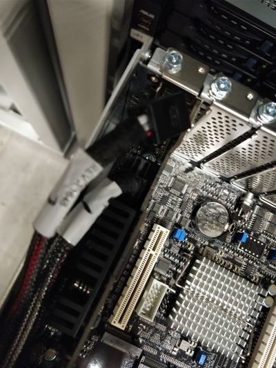
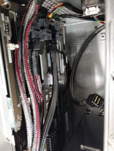
Regarding the hardware setup, this involved disconnecting from the front expander board, the cable connecting it to the rear board. We also disconnected the port 2 cable from the PIKE card. In summary, port 1 from the PIKE remained connected to the front expander and the rear expander was disconnected.
Note that both backplanes remained powered throughout the process.
The following images document the process (click images for larger versions).
|
|
| PIKE ports: port 1 connected to front expander; port 2 disconnected | Ports in front backplane: one connected to PIKE port 1; other 2 cables disconnected |
|
|
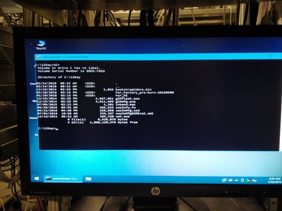
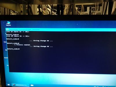
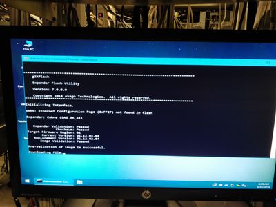
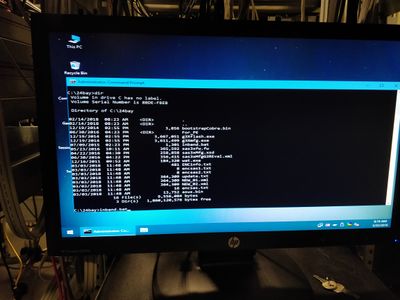
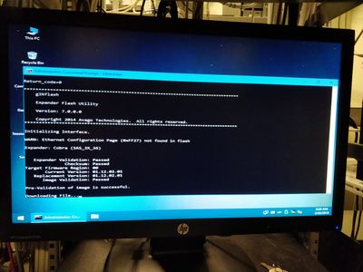
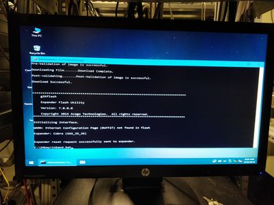
| Listing of 24-bay firmware directory | Output from the flashing process (24-bay backplane) |
| |
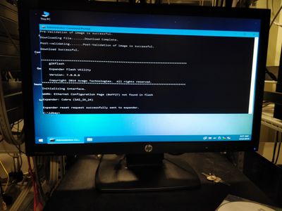
| Output from the flashing process (24-bay backplane) (end) |
Flashing the REAR expander
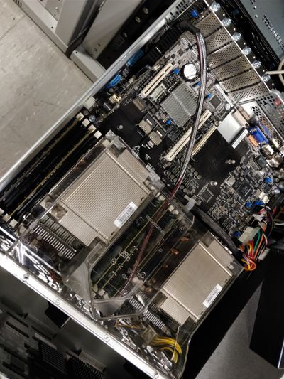
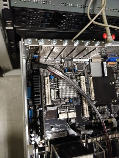
Regarding the hardware setup, this involved completely disconnecting the front backplane from the PIKE card. The cable coming from the rear expander was directly connected to the PIKE's port 2 (to enable access to the rear expander, the support for the fans was shifted and the airflow guide over processors and memory was also temporarily removed).
Note that both backplanes remained powered throughout the process.
The following images document the process (click images for larger versions).
|
|
| Rear backplane cable connection to PIKE port 2 | Rear backplane cable connection to PIKE port 2 (detail) |
The Update Procedure for the PIKE card
This is a matter of booting the machine with the FreeDOS disk (bundled with the machine) and running the included DOS app to flash the new firmware version. The procedure used the following materials:
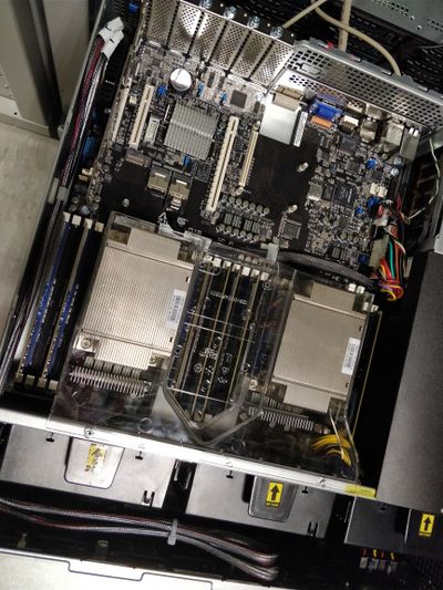
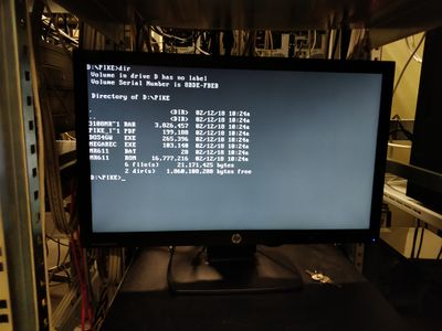
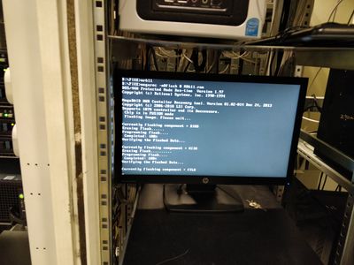
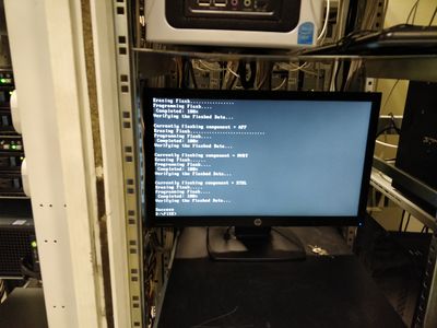
Before flashing the PIKE card, the hardware was reassembled as in its factory configuration. The following images document the flashing process.
|
| Assembled machine (minus screws) |
|
|
| Listing of PIKE firmware directory | Output from the flashing process (start) |
| |
| Output from the flashing process (end) |
Issues
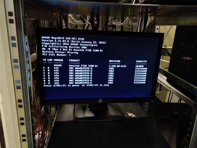
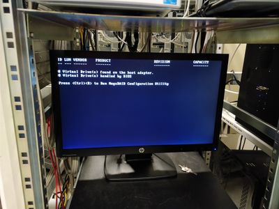
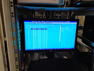
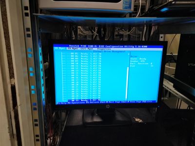
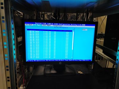
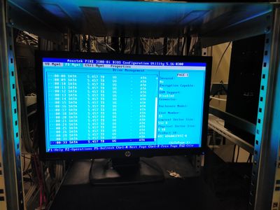
Although all the above procedures apparently finish successfully, after performing the updates, the results are not acceptable. Namely, the PIKE does not identify the backplanes as before and does not even list the disks connected to the rear expander. In addition, the d isks connected to the front expander appear with "strange" addresses (for instance, addresses do not start at zero and some addresses are missing).
The following images show aspects of the problem:
|
|
| PIKE boot (page 1) | PIKE boot (page 3 -- page 2 was just a list of disks) |
|
|
| PIKE configuration utility (page 1 - VD view) | PIKE configuration utility (page 2 - VD view) |
|
|
| PIKE configuration utility (page 1 - PD view) | PIKE configuration utility (page 2 - PD view) |
